This chapter describes the general parameterization options for value stream objects. The symbols described here for the parameterization of objects are the same for all value stream objects.
The following table lists the existing symbols and explains them:
Button |
Description |
|
The Icon Editor symbol opens the Icon Editor. Here the icon can be rotated or mirrored or an alternative icon can be chosen. Also, a custom size can be set for the icon.
Figure 1 - Icon editor |
|
The Delete Symbol deletes the object |
|
Via the Measurement symbol measurement points in the value stream can be set •First click defines the object as measurement start point •Second click defines the object as measurement end point •Third click defines the object as measurement start and end point •Fourth click removes the previously created measuring points from the object |
|
The Edit Symbol opens the editing menu of the object. Detailed instructions for this menu can be found in the chapter Editing value stream objects |
|
The Add Images Symbol opens a dialog in which either a picture can be taken with the help of a web cam, or an image can be loaded from Windows Explorer.
Figure 2 - Camera dialog |
|
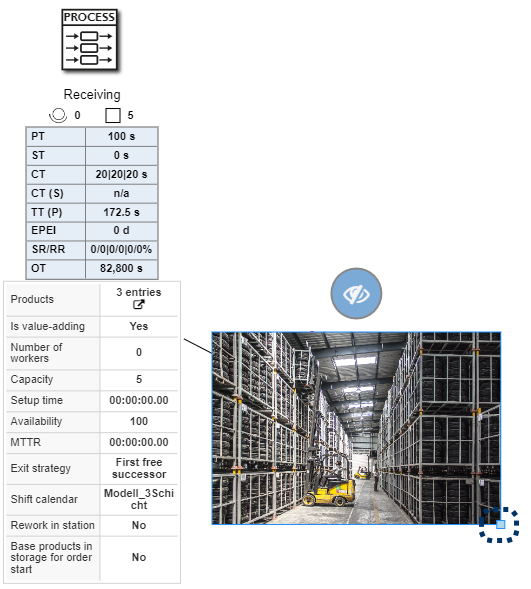
The Show Images symbol opens the photo gallery of the object. Photos that were previously created are displayed here.
Figure 3 - Add Photos With the option Show in Model, photos can also be displayed and arranged directly in the modeling interface (see Figure 5). Furthermore, the anchor at the lower right edge can be used to adjust the size of the image. |
|
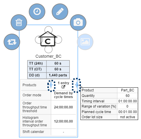
The Hide symbol hides extended product information/images (if displayed) |
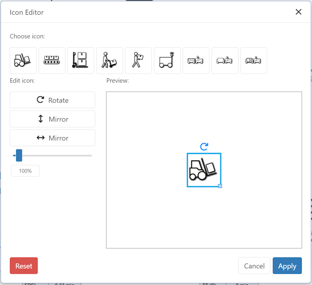


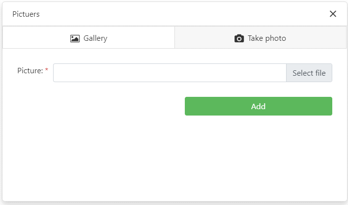

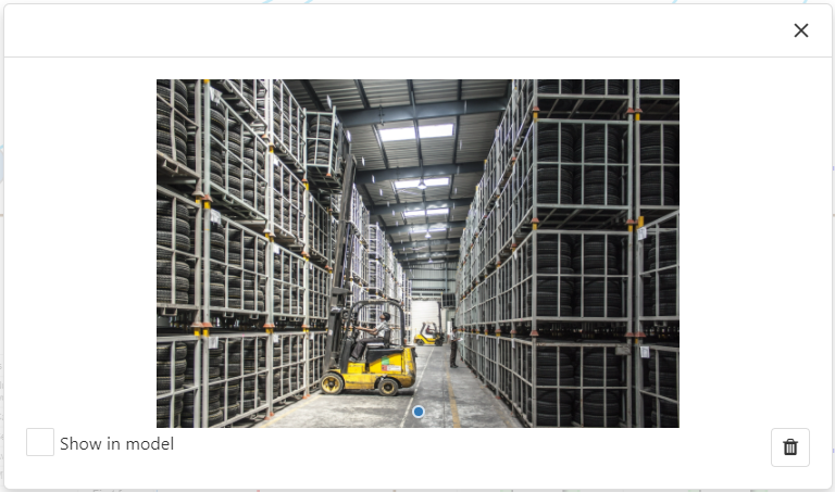

Figure 4 shows a customer object with the respective object symbols.
Furthermore, if defined for the object, a detail window containing information about the respective product can be displayed by clicking on the product name.
The size of the parameter window can be adjusted using the slider (see marking in Figure 3).
In addition, for processes under the respective name of the object also the number of workers ![]() and the number of stations
and the number of stations ![]() are displayed.
are displayed.
Figure 4 - Object symbols customer object |
Figure 5 - Show images in the modeling interface |
© SimPlan AG - Hanau District Court, Commercial Register (Part B) 6845 - info@simplan.de - www.simplan.de/en